· AtlasPCB Engineering · Engineering · 9 min read
IPC-6013 Flexible Circuit Quality Standard: Design Rules and Acceptance Criteria
Complete guide to IPC-6013 qualification requirements for flexible and rigid-flex PCBs. Covers Class 1/2/3 acceptance criteria, bend radius rules, conductor spacing, coverlay requirements, and testing protocols for flex circuit manufacturing.
Introduction: Why IPC-6013 Matters for Flex Circuits
Flexible printed circuits operate under unique mechanical stresses that rigid boards never experience. They bend, fold, twist, and sometimes flex continuously for millions of cycles. Standard rigid board specifications (IPC-6012) cannot adequately address these challenges—which is exactly why IPC-6013 exists as a dedicated standard for flexible circuit qualification.
IPC-6013, titled “Qualification and Performance Specification for Flexible/Rigid-Flexible Printed Boards,” defines the quality requirements that ensure flex circuits perform reliably throughout their intended service life. Whether your [flex PCB design]/blog/flex-pcb-design-guidelines/) is a simple single-sided cable replacement or a complex 8-layer rigid-flex for aerospace, IPC-6013 provides the acceptance criteria manufacturers must meet.
This guide walks through the standard’s critical requirements, helping both designers and procurement engineers understand what to specify and verify.
IPC-6013 Performance Classes
Class Definitions
Like other IPC performance specifications, IPC-6013 defines three classes with progressively stricter requirements:
Class 1 — General Electronic Products:
- Consumer electronics, IoT devices, disposable medical sensors
- Functional performance is required but cosmetic imperfections are acceptable
- Most lenient acceptance criteria
- Typical applications: phone flex cables, LED strips, basic interconnects
Class 2 — Dedicated Service Electronic Products:
- Industrial equipment, telecommunications, automotive (non-safety)
- Extended life and reliable operation required
- Moderate acceptance criteria balancing cost and reliability
- Typical applications: laptop hinges, automotive dashboards, medical monitors
Class 3 — High-Reliability Electronic Products:
- Aerospace, military, medical implants, safety-critical automotive
- Continued performance and no failure acceptable
- Most stringent acceptance criteria
- Typical applications: satellite flex harnesses, pacemaker interconnects, flight controls
Key Acceptance Criteria by Class
| Parameter | Class 1 | Class 2 | Class 3 |
|---|---|---|---|
| Conductor width reduction | ≤30% | ≤30% | ≤20% |
| Conductor thickness reduction | ≤30% | ≤20% | ≤10% |
| Min. annular ring (external) | 0μm (breakout OK) | 25μm | 50μm |
| Min. annular ring (internal) | 0μm | 0μm (tangent OK) | 25μm |
| Dielectric thickness min. | 60% of spec | 80% of spec | 80% of spec |
| Coverlay registration | ±250μm | ±150μm | ±75μm |
| Lifted pads | Acceptable if functional | Minor acceptable | Not acceptable |
| Measles/crazing | Acceptable | Minimal | Not acceptable |
| Plating voids (barrel) | ≤50% | ≤25% | ≤5% (one void) |
Flex-Specific Construction Requirements
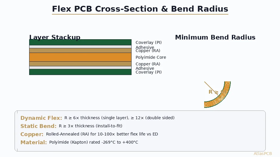
Bend Radius Requirements
The minimum bend radius is the most critical flex-specific parameter in IPC-6013:
Static flex (installed and not repeatedly flexed):
| Construction | Minimum Bend Radius |
|---|---|
| Single-layer flex (unplated) | 3× circuit thickness |
| Single-layer flex (plated) | 6× circuit thickness |
| Double-sided flex | 10× circuit thickness |
| Multilayer flex (3+ layers) | 12× circuit thickness |
| Rigid-flex transition zone | 15× flex section thickness |
Dynamic flex (repeatedly flexed in service):
| Construction | Minimum Bend Radius |
|---|---|
| Single-layer flex | 12× circuit thickness |
| Double-sided flex | 20× circuit thickness |
| Multilayer flex | 25× circuit thickness |
Design implications:
- A 0.2mm thick single-sided flex can bend to R=0.6mm (static) or R=2.4mm (dynamic)
- A 0.4mm thick 4-layer flex requires R=4.8mm static minimum
- Conductors in bend zones should run perpendicular to the bend axis
- Avoid plated through-holes within 2× bend radius of flex zone edge
Conductor Routing in Flex Zones
IPC-6013 Section 3.4 establishes conductor design rules for flex areas:
Single-sided flex:
- Conductors perpendicular to bend axis preferred
- Stagger conductors on opposite sides (don’t stack)
- Minimum conductor width in flex zone: 100μm (Class 3)
- No acute angle bends in conductor routing within flex zone
Double-sided/multilayer flex:
- Conductors on different layers should be staggered (not directly aligned)
- I-beam effect (stacked conductors) dramatically reduces flex life
- Crosshatch ground planes instead of solid copper in flex zones
- Via placement prohibited within flex zone for dynamic applications
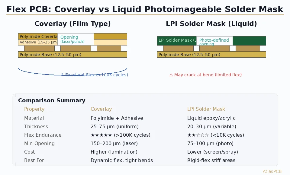
Coverlay Requirements
Coverlay (the flexible version of solder mask) has specific IPC-6013 requirements:
Material requirements:
- Base film: Polyimide (25μm min) or polyester (50μm min for Class 1/2 only)
- Adhesive: Acrylic, epoxy, or modified epoxy (12-25μm typical)
- Total coverlay thickness: 37-75μm typical
- Peel strength: ≥0.5 N/mm (Class 3), ≥0.35 N/mm (Class 2)
Opening registration:
- Pad exposures must maintain minimum insulation distance
- Adhesive squeeze-out must not contaminate exposed pads
- Maximum adhesive flow: 200μm (Class 2), 100μm (Class 3)
- Coverlay overlap onto conductors: minimum 250μm per side
Lamination integrity:
- No delamination between coverlay and conductor
- No trapped air bubbles >1mm diameter
- Uniform adhesive flow around conductors
- Cross-section verification: adhesive fills between conductors completely
Need IPC-6013 Compliant Flex PCB Manufacturing?
AtlasPCB manufactures IPC-6013 Class 2 and Class 3 flexible and rigid-flex circuits with full qualification testing, microsection analysis, and flex endurance validation.
Get Flex PCB Quote →Material Requirements per IPC-6013
Base Film Specifications
| Material | Dk (1GHz) | Thickness Options | Temp Range | Flex Endurance |
|---|---|---|---|---|
| Polyimide (Kapton) | 3.4 | 12.5, 25, 50, 75, 125μm | -269°C to +400°C | Excellent |
| Modified PI (AP type) | 3.3 | 25, 50μm | -65°C to +250°C | Excellent |
| PEN (polyethylene naphthalate) | 2.9 | 25, 50, 75μm | -40°C to +155°C | Good |
| LCP (liquid crystal polymer) | 2.9-3.1 | 25, 50μm | -40°C to +280°C | Good |
| Polyester (PET) | 3.2 | 25, 50, 75μm | -40°C to +105°C | Moderate |
IPC-6013 requirements:
- Class 3 specifies polyimide base film only (polyester not permitted)
- Dimensional stability: ≤0.05% after thermal stress (288°C, 10s)
- Moisture absorption: ≤2.5% at equilibrium
- Dielectric strength: ≥3000V/mil minimum
Copper Foil Requirements
Conductor types specified in IPC-6013:
| Type | Description | Typical Use | Flex Endurance |
|---|---|---|---|
| RA (rolled annealed) | Large grain structure | Dynamic flex | Best |
| ED (electrodeposited) | Columnar grain structure | Static flex only | Moderate |
| HA (HTE annealed) | Modified ED with treatment | Semi-dynamic | Good |
Key specification:
- Class 3 dynamic flex MUST use RA copper — ED copper cracks under repeated flexing
- Minimum elongation: 10% (RA copper typically achieves 15-25%)
- Tensile strength: 195-255 MPa for 1oz RA copper
- Surface roughness: Rz ≤ 2μm for fine-line imaging
Adhesive Systems
| Adhesive Type | Operating Temp | Peel Strength | Flex Endurance | Cost |
|---|---|---|---|---|
| Acrylic | -65 to +150°C | 0.7-1.2 N/mm | Good | Low |
| Modified epoxy | -55 to +177°C | 0.9-1.5 N/mm | Moderate | Medium |
| Adhesiveless (cast PI) | -269 to +400°C | N/A (integral) | Excellent | High |
| Thermoplastic PI | -65 to +250°C | 0.8-1.3 N/mm | Good | High |
IPC-6013 Class 3 notes:
- Adhesiveless construction preferred for maximum reliability
- If adhesive used, must maintain >0.5 N/mm peel after thermal stress
- Adhesive flow control critical — excessive flow contaminates pads
- Z-axis CTE of adhesive must be considered for via reliability
Testing Requirements
Qualification Testing (IPC-6013 Section 3.8)
Before production release, flex circuits must pass qualification testing:
Visual and dimensional:
- 100% visual inspection per acceptance criteria tables
- Dimensional measurement at 23°C ±3°C, 50% ±5% RH
- Feature location tolerance verification
- Coverlay registration measurement
Microsection analysis:
- Minimum 3 cross-sections per qualification lot
- Verify: conductor width/thickness, dielectric spacing, plating thickness
- Check: barrel fill, knee coverage, annular ring, conductor crack
- Rigid-flex transition zone must be microsectioned
Thermal stress testing:
- Float on solder at 288°C for 10 seconds (Class 3) or 260°C for 10 seconds (Class 2)
- No delamination, blistering, or measles after thermal stress
- Microsection after thermal stress to verify integrity
- Thermal cycling: -65°C to +125°C, 100 cycles minimum (Class 3)
Flex endurance testing:
- Per IPC-TM-650, Method 2.4.3
- Flex circuit cycled at specified bend radius
- Monitor continuity and insulation resistance during flexing
- Class 3 dynamic flex: must survive minimum cycles per design specification
- Failure defined as >10% resistance increase or open circuit
Electrical testing:
- Continuity: All circuits must conduct (maximum resistance per specification)
- Insulation resistance: ≥500MΩ between conductors (≥2MΩ after humidity exposure)
- Dielectric withstand: 500V DC minimum for 60 seconds without breakdown
- Characteristic impedance: ±10% of target (if controlled impedance specified)
In-Process Testing
During production, IPC-6013 requires:
- Electrical test (continuity + isolation) on 100% of circuits
- Visual inspection per class requirements
- Dimensional verification on first article and periodic samples
- Peel strength testing on production coupons
Rigid-Flex Specific Requirements
Transition Zone Design
The rigid-to-flex transition is the most failure-prone area in rigid-flex construction:
IPC-6013 transition requirements:
- No plated through-holes within 0.5mm of rigid-flex boundary (Class 3)
- Adhesive or prepreg fillet must cover transition edge
- Flex layers must extend minimum 1mm into rigid section
- No 90° corners at transition — radius or chamfer required
Two construction methods:
Book-binder (preferred for Class 3):
- Flex layers are continuous, not bonded in flex zone
- Each flex layer can move independently during bending
- Better flex endurance — no through-thickness stress
- Requires careful layer registration during rigid lamination
Bonded/adhesive construction:
- All flex layers laminated together in flex zone
- Simpler manufacturing but increased stiffness
- Limited to static or low-cycle dynamic applications
- Higher risk of delamination at transition under flex stress
Via Restrictions in Rigid-Flex
| Zone | Through Vias | Blind Vias | Microvias |
|---|---|---|---|
| Rigid section | Allowed | Allowed | Allowed |
| Transition (1mm from edge) | Not recommended | Limited | Allowed with analysis |
| Flex zone (static) | Not allowed | Not applicable | Not applicable |
| Flex zone (dynamic) | Not allowed | Not applicable | Not applicable |
Exceptions:
- Through-vias in flex zone may be specified if flex section is stiffened and not bent
- Button plating (pad-only plating without barrel) permitted in some static flex applications
- [Microvia technology]/blog/hdi-microvia-stacked-vs-staggered-reliability-en/) may be used in rigid sections per IPC-6012
Design for IPC-6013 Compliance
Critical Design Rules
Conductor design:
- Use teardrops at all pad-to-trace transitions (25-50μm extension)
- Minimum conductor width in flex zone: 100μm (Class 3)
- Conductor spacing minimum: 100μm (Class 3) — verify against voltage requirements
- Avoid isolated pads without anchor traces in flex zones
- Route traces at 45° angles to prevent stress concentration
Pad design:
- Annular ring ≥50μm (Class 3 external), ≥25μm (Class 3 internal)
- Anchor pads with minimum 2 traces entering from different directions
- Thermal relief pads for hand-soldering access
- No via-in-pad in flex zone (use dogbone breakout)
Stiffener design:
- Stiffeners support component areas and connectors
- Overlap flex by minimum 2mm per side
- Material: FR-4, polyimide, stainless steel, or aluminum
- Attach with pressure-sensitive adhesive (PSA) or thermosetting adhesive
- Specify thickness based on required support and assembly method
Impedance Control in Flex Circuits
IPC-6013 references [impedance control]/blog/how-to-specify-impedance-pcb/) with flex-specific considerations:
- Coverlay thickness variation affects impedance more than rigid solder mask
- Adhesive flow around traces changes effective dielectric thickness
- RA copper surface roughness affects conductor loss at high frequencies
- Temperature-dependent Dk of polyimide (±3% from -40°C to +85°C)
- Tolerance: ±10% typical for Class 2, ±7% achievable for Class 3 with controls
Common Non-Conformances and Corrective Actions
Top 5 IPC-6013 Failures in Production
Coverlay adhesion failure (30% of rejections):
- Root cause: Surface contamination before lamination
- Correction: Plasma treatment, verify cleanliness before lamination
Conductor width violation (25% of rejections):
- Root cause: Over-etching in fine-line imaging
- Correction: Etch chemistry control, photoresist optimization
Flex endurance failure (20% of rejections):
- Root cause: ED copper used instead of RA, or bend radius violated
- Correction: Material verification, design review for bend radius compliance
Delamination after thermal stress (15% of rejections):
- Root cause: Moisture absorption before lamination, inadequate bake
- Correction: Pre-lamination bake (125°C, 4h), humidity control in storage
Dimensional instability (10% of rejections):
- Root cause: Stress relief during thermal processing
- Correction: Pre-shrink base materials, control process temperatures
Specifying IPC-6013 in Your Design Package
Required Documentation
When ordering flex circuits to IPC-6013, specify:
- Performance class (1, 2, or 3) on fabrication drawing
- Service condition (static, dynamic, or semi-dynamic flex)
- Flex endurance requirement (number of cycles at specified radius)
- Material callouts (polyimide type, copper type, adhesive type)
- Testing requirements beyond standard (thermal cycling, vibration, etc.)
- Dimensional tolerances per feature location tables
- Impedance requirements with test coupon specifications
- Qualification test plan reference
Ordering Example (Fabrication Note)
FLEX CIRCUITS SHALL CONFORM TO IPC-6013 CLASS 3 TYPE 4 (MULTILAYER FLEX)
BASE MATERIAL: POLYIMIDE PER IPC-4204/11, 25μm ±3μm
COPPER: 1oz RA (ROLLED ANNEALED) PER IPC-4562 TYPE RA
COVERLAY: POLYIMIDE/ACRYLIC PER IPC-4203/11, 12μm PI + 15μm ADHESIVE
FLEX ENDURANCE: 50,000 CYCLES MIN AT R=5mm, 180° FLEX
QUALIFICATION: PER IPC-6013 SECTION 3.8, THERMAL STRESS + MICROSECTION
Conclusion
IPC-6013 provides the comprehensive framework for ensuring flex circuit quality and reliability. Key takeaways for designers and procurement:
- Specify the right class — over-specifying Class 3 when Class 2 suffices increases cost 30-50%
- Design for the bend — minimum bend radius is the most common Class 3 violation
- Material selection matters — RA copper and adhesiveless construction enable best flex endurance
- Transition zones are critical — most rigid-flex failures occur at the rigid-to-flex boundary
- Test early — qualification testing should happen before committing to production tooling
Planning a flex or rigid-flex design? AtlasPCB’s engineering team can review your design for IPC-6013 compliance before fabrication, identifying potential violations that could cause qualification failure. Request a design review — our DFM engineers specialize in complex flex and [rigid-flex constructions]/blog/flex-pcb-design-guidelines/).
Further Reading
- [PCB Rigid-Flex Bend Zone Reliability: Design Rules, Material Selection & Lifecycle Testing]/blog/pcb-rigid-flex-bend-zone-reliability/)
- [Dynamic Flex PCB Design — Bend Radius, Material Selection, and Reliability]/blog/dynamic-flex-pcb-design-bend-radius-reliability/)
- [Rigid-Flex PCB Design Guide: Bend Radius, Layer Transitions, and Reliability for Wearables and Aerospace]/blog/rigid-flex-pcb-design-bend-radius-reliability-guide/)
- [Rigid-Flex PCB Design: Stackup, Bend Rules, and Manufacturing Guidelines]/blog/rigid-flex-pcb-design/)
- [Flex PCB Design Guidelines: Bend Radius, Conductor Routing, Stiffeners, and Material Selection]/blog/flex-pcb-design-guidelines/)
- Rigid-Flex PCB Manufacturing
About AtlasPCB — We specialize in complex PCB manufacturing for HDI, RF, and high-reliability applications. Explore our rigid-flex PCB manufacturing, or get an full PCB manufacturing capabilities . Every order includes free engineering review. Get your quote.
Reviewed by AtlasPCB Engineering Team — IPC-certified manufacturing specialists with 15+ years of production experience in HDI, RF, and high-reliability PCB fabrication. Content based on factory floor data and real customer design reviews.
- IPC-6013
- flex PCB
- rigid-flex
- quality standard
- acceptance criteria
- flexible circuits
- coverlay