· AtlasPCB Engineering · Engineering · 6 min read
IPC-4101 Laminate Specification Guide: Selecting the Right PCB Base Material
Complete guide to IPC-4101 laminate slash sheets for PCB designers. Covers material classification, key parameters (Tg, Td, Dk, Df, CTE, T-288), and selection criteria for high-speed, high-frequency, automotive, and aerospace applications.

Why IPC-4101 Matters for PCB Designers
Every PCB starts with a base material — the laminate and prepreg that form the structural backbone and dielectric layers of your board. While many designers simply specify “FR-4” on their fabrication notes, this generic callout encompasses a vast range of materials with dramatically different performance characteristics.
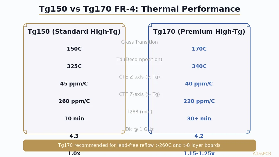
The difference between a bargain FR-4 (Tg 130°C, Td 300°C) and a premium high-speed laminate (Tg 200°C, Td 380°C, Dk 3.3 @ 10GHz) can mean the difference between a product that survives 1000 thermal cycles and one that delaminates at 200 cycles. IPC-4101 provides the framework to specify exactly what you need.
IPC-4101C (current revision) defines over 80 slash sheets covering:
- Standard and high-Tg epoxy glass (FR-4 family)
- Polyimide laminates (high-temperature)
- PTFE/ceramic composites (RF/microwave)
- Cyanate ester and BT blends (high-speed)
- Halogen-free formulations (environmental compliance)
- Metal-core and thermally enhanced substrates
Understanding the Slash Sheet System
Structure of IPC-4101
Each slash sheet (designated as /XX or /XXX) defines a material category with:
- Reinforcement type (E-glass, S-glass, quartz, PTFE woven, non-woven)
- Resin system (epoxy, polyimide, PTFE, cyanate ester, PPE, BT)
- Key property minimums/maximums
- Test method references (IPC-TM-650 procedures)
The slash sheet does NOT specify a brand name. “/126” can be fulfilled by Isola IS415, Shengyi S1000-2M, Panasonic R-1755V, or any material meeting the published requirements. This enables competitive sourcing without sacrificing quality.
Most Common Slash Sheets for PCB Design
| Slash Sheet | Description | Typical Products |
|---|---|---|
| /21 | Woven E-glass / Epoxy, FR-4, Tg ≥ 110°C | Standard consumer PCBs |
| /24 | Woven E-glass / PTFE, Dk 2.1-2.4 | RF/microwave boards |
| /26 | Woven E-glass / PTFE, Dk 2.4-2.8 | RF/microwave boards |
| /97 | Ceramic-filled PTFE, Dk 3.0-3.5 | Antenna substrates |
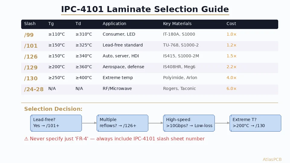
| /99 | Woven E-glass / Epoxy, FR-4, Tg ≥ 110°C | Low-cost general purpose |
| /101 | Woven E-glass / Epoxy, Tg ≥ 150°C | Lead-free compatible |
| /121 | Woven E-glass / Epoxy, Tg ≥ 170°C | Multilayer, high reliability |
| /124 | Woven E-glass / Epoxy, Tg ≥ 150°C, Halogen-free | Eco-compliance |
| /126 | Woven E-glass / Filled Epoxy, Tg ≥ 150°C, Td ≥ 340°C | Automotive, server |
| /129 | Woven E-glass / Filled Epoxy, Tg ≥ 200°C, Td ≥ 360°C | Aerospace, HDI |
| /130 | Woven E-glass / Polyimide, Tg ≥ 250°C | Extreme temperature |
Key Material Properties Defined
Glass Transition Temperature (Tg):
- Temperature where resin transitions from glassy to rubbery state
- Above Tg: CTE increases dramatically (z-axis expansion accelerates)
- Design rule: Tg should be ≥25°C above maximum sustained operating temperature
- Test method: DSC (IPC-TM-650 2.4.25) or TMA (2.4.24)
Decomposition Temperature (Td):
- Temperature at 5% weight loss (resin degradation onset)
- Critical for lead-free reflow survivability (peak ~245-260°C)
- Minimum for lead-free: Td ≥ 325°C; recommended ≥ 340°C
- Test method: TGA (IPC-TM-650 2.4.24.6)
Z-axis CTE (Coefficient of Thermal Expansion):
- Expansion in the thickness direction — stresses plated through-hole barrels
- Below Tg: typically 40-60 ppm/°C for FR-4
- Above Tg: can spike to 200-300 ppm/°C for standard FR-4
- Filled resins (/126, /129): 30-45 ppm/°C below Tg, <200 ppm/°C above
- Critical for thick boards (>2.0mm) and high-aspect-ratio vias (>8:1)
Dielectric Constant (Dk) and Loss Tangent (Df):
- Dk determines impedance and signal velocity
- Df determines signal attenuation (insertion loss)
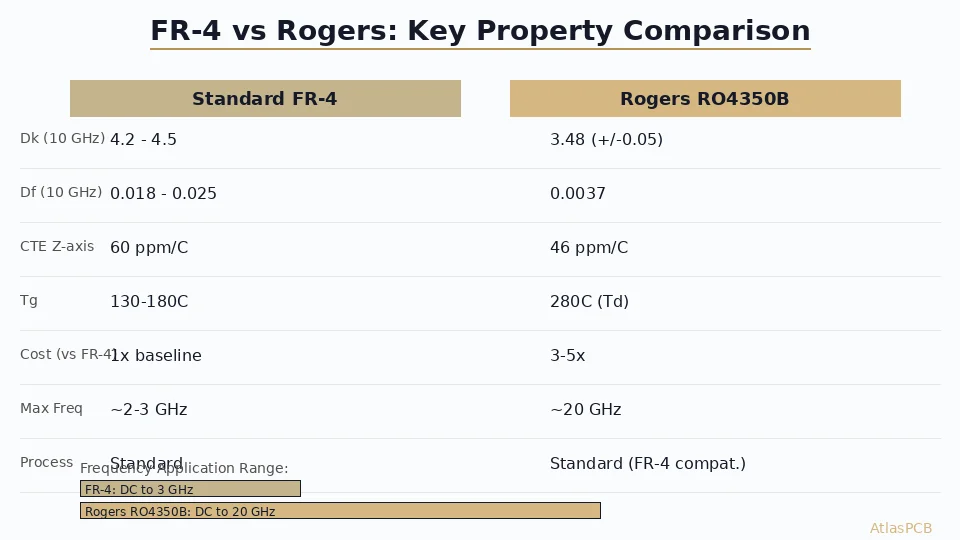
- Standard FR-4: Dk ~4.2-4.5, Df ~0.020-0.025 @ 1GHz
- Low-loss materials: Dk ~3.3-3.8, Df ~0.003-0.008 @ 10GHz
- Test method: IPC-TM-650 2.5.5.9 (stripline resonator) or 2.5.5.13 (split-post)
T-288 (Time to Delamination):
- Time the material survives at 288°C before delamination occurs
- Minimum for lead-free: >5 minutes
- High-reliability: >15 minutes
- Indicates thermal robustness during reflow and rework
- Test method: IPC-TM-650 2.4.24.1
Moisture Absorption:
- Weight gain after 24h immersion at 23°C (IPC-TM-650 2.6.2.1)
- Standard FR-4: 0.10-0.15%
- Low-moisture materials: <0.08%
- High absorption increases Dk and CAF risk
Material Selection Decision Tree
Step 1: Determine Operating Environment
| Application | Min Tg | Min Td | Z-CTE | Dk/Df Priority |
|---|---|---|---|---|
| Consumer electronics | 130°C | 310°C | <65 ppm | Low priority |
| Telecom/networking | 150°C | 340°C | <55 ppm | High (>10Gbps) |
| Automotive (under-hood) | 170°C | 350°C | <50 ppm | Medium |
| Aerospace/defense | 200°C+ | 370°C+ | <45 ppm | Application-specific |
| LED lighting | 130°C | 310°C | N/A | N/A |
| RF/microwave | Application | dependent | N/A | Critical (Dk tolerance) |
Step 2: Assembly Compatibility
Count the number of reflow cycles your board will experience:
- 1 reflow (single-side SMT): /99 or /101 adequate
- 2 reflows (double-side SMT): /101 minimum, /126 recommended
- 3+ reflows (rework, BGA reballing): /126 or /129 required
Lead-free reflow peak temperature considerations:
- SAC305: 245-250°C peak → Td ≥ 330°C with margin
- High-Ag SAC: 240-245°C peak → Td ≥ 325°C
- SnBi low-temp: 170-180°C peak → /99 adequate
Step 3: Electrical Requirements
For impedance-controlled designs:
- Standard digital (<1 Gbps): Any FR-4 is fine; use Dk 4.2 nominal
- High-speed (1-10 Gbps): Specify Dk tolerance ±5%; mid-loss (/126 class)
- Very high-speed (10-56 Gbps): Low-loss materials (Df <0.008); Megtron 6, Tachyon class
- RF/Microwave: PTFE-based (/24-/28) or ceramic-filled (/97); Dk tolerance ±2%
Step 4: Reliability Requirements
| Reliability Level | Recommended Slash Sheets | Typical Materials |
|---|---|---|
| Commercial | /99, /101 | IT-180A, S1000-2 |
| Industrial | /101, /121, /126 | IS415, S1000-2M |
| Automotive | /126, /129 | IS415, Megtron 6, R-5775K |
| Mil/Aero | /129, /130 (polyimide) | IS408HR, Arlon 85NT |
| Space | /130 + special qualification | Polyimide, CE/BT blends |
Need Help Selecting the Right Laminate?
AtlasPCB engineers review your stackup and recommend IPC-4101 compliant materials optimized for your performance, reliability, and budget requirements.
View Our Material Capabilities →Common Specification Mistakes
Mistake 1: Specifying Just “FR-4”
“FR-4” only guarantees UL 94V-0 flammability and woven E-glass/epoxy construction. It tells the fabricator nothing about:
- Tg (could be 130°C or 180°C)
- Td (could be 290°C or 360°C)
- CTE z-axis properties
- Lead-free reflow capability
- Electrical loss characteristics
Fix: Always specify IPC-4101 slash sheet number on your fabrication drawing.
Mistake 2: Over-specifying Material
Calling out Isola IS415 (or any proprietary name) when /126 requirements are sufficient creates:
- Single-source dependency
- Higher cost (no competitive bidding)
- Longer lead times
- Qualification risk if material gets discontinued
Fix: Specify the IPC-4101 slash sheet. Add “or equivalent” after a trade name if you must reference specific materials for qualification purposes.
Mistake 3: Ignoring Prepreg Compatibility
Mixing laminates and prepregs from different systems can cause:
- Delamination from resin incompatibility
- CTE mismatch stress between layers
- Unpredictable Dk profiles in the stackup
Fix: Specify that core and prepreg must be from the same material system or verify compatibility with the fabricator’s process engineer.
Mistake 4: Not Specifying Dk at the Correct Frequency
Material datasheets report Dk at 1 MHz, 1 GHz, or 10 GHz. These values differ significantly:
- Standard FR-4: Dk 4.7 @ 1MHz → 4.2 @ 1GHz → 4.0 @ 10GHz
- Low-loss: Dk 3.8 @ 1MHz → 3.5 @ 1GHz → 3.4 @ 10GHz
Fix: Specify Dk at your operating frequency. For impedance calculations, use Dk at the knee frequency of your signals (≈0.35 / rise time).
Practical Fabrication Notes
Material Availability by Region
Not all slash sheets have equal global availability:
| Region | Readily Available | May Require Lead Time |
|---|---|---|
| China/Asia | /99, /101, /126 | /129, /130 |
| North America | /99, /101, /121, /126, /129 | /130, PTFE |
| Europe | /101, /126 | /99 (less common), /130 |
For production volumes, discuss material availability with your fabricator during design phase — not after Gerber release.
Cost Impact
Relative cost multipliers (vs. standard /99 FR-4 = 1.0×):
| Slash Sheet / Material Class | Cost Multiplier |
|---|---|
| /99 Standard FR-4 | 1.0× |
| /101 Mid-Tg | 1.1-1.3× |
| /126 High-reliability | 1.3-1.6× |
| /129 Ultra-high performance | 1.8-2.5× |
| /130 Polyimide | 3.0-5.0× |
| Low-loss (Megtron 6 class) | 2.0-3.0× |
| PTFE (/24-/28) | 4.0-8.0× |
Specifying on Fabrication Drawings
Best practice format in your fab notes:
MATERIAL: IPC-4101/126, Tg ≥ 150°C (DSC), Td ≥ 340°C (TGA)
Dk: 4.0 ± 0.15 at 1GHz (reference stackup)
CORE THICKNESS: Per stackup drawing (tolerance ±10%)
PREPREG: Same material system as core
For critical designs, add:
T-288: > 15 minutes
Z-CTE: < 50 ppm/°C (below Tg)
MOISTURE ABSORPTION: < 0.12%
COPPER FOIL: RTF or STD profile per layer (see stackup)
Key Takeaways
- Always specify IPC-4101 slash sheet — never just “FR-4” on production drawings
- Match material to assembly process — lead-free requires /101 minimum; multiple reflows need /126+
- Consider the full property set — Tg alone doesn’t predict reliability; Td and z-CTE matter more for via survival
- Balance cost and performance — don’t specify /129 when /126 meets all requirements
- Verify availability early — exotic slash sheets may have 4-8 week lead times
Further Reading
- PCB Stackup Symmetry and Balanced Lamination for Warpage Control
- High-Frequency PCB Material Selection: Rogers vs PTFE
- HDI PCB Stackup Design: Advanced Configurations
AtlasPCB stocks a comprehensive range of IPC-4101 qualified laminates from /99 through /130, with fast-turn availability on high-reliability materials. Get a quote with guaranteed material traceability.
About AtlasPCB — We specialize in complex PCB manufacturing for HDI, RF, and high-reliability applications. Explore our impedance-controlled PCB manufacturing, or get an full PCB manufacturing capabilities . Every order includes free engineering review. Get your quote.
Reviewed by AtlasPCB Engineering Team — IPC-certified manufacturing specialists with 15+ years of production experience in HDI, RF, and high-reliability PCB fabrication. Content based on factory floor data and real customer design reviews.
- IPC-4101
- PCB laminate
- FR-4
- high-Tg
- base material
- PCB material selection
- prepreg
- high-speed PCB