· AtlasPCB Engineering · Engineering · 8 min read
IPC-2581 Digital Twin: PCB Data Exchange Standard for Smart Manufacturing and Industry 4.0
Complete guide to IPC-2581 — the intelligent PCB data exchange standard enabling digital twins, automated DFM, and lights-out manufacturing. Learn how IPC-2581 replaces Gerber files, its structure, adoption benefits, and implementation for PCB design-to-manufacturing workflows.
Introduction: The PCB Industry’s Data Problem
For over four decades, the PCB industry has relied on Gerber files — a format invented in 1980 to drive photoplotters. We design in intelligent 3D environments with complete electrical and physical data, then deliberately strip that intelligence away to generate “dumb” 2D image files for manufacturing. The manufacturer then spends hours reverse-engineering design intent from these images.
This process is absurd. It’s like sending an architect’s blueprints to a builder as a stack of photographs — then wondering why things get misinterpreted.
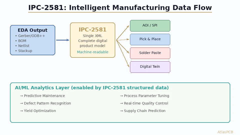
IPC-2581 — officially the Digital Product Model Exchange (DPMX) standard — solves this problem by maintaining full design intelligence from EDA tool through manufacturing. It creates a digital twin of your PCB that machines can read, software can analyze, and people can trust without manual interpretation.
This guide explains everything you need to know about IPC-2581: what it contains, how it works, why adoption is accelerating in 2026, and how to implement it in your design-to-manufacturing workflow.
What’s Wrong with Gerber Files?
Before understanding why IPC-2581 matters, let’s clearly define what Gerber files lack:
Information That Gerbers Cannot Carry
| Critical Information | Available in Gerber? | Available in IPC-2581? |
|---|---|---|
| Layer stackup definition | ❌ Separate document | ✅ Embedded |
| Material specifications | ❌ Separate document | ✅ Embedded |
| Net connectivity (netlist) | ❌ Separate IPC-D-356 file | ✅ Embedded |
| Impedance requirements | ❌ Fab drawing note | ✅ Per-trace specification |
| Component data (BOM) | ❌ Separate spreadsheet | ✅ Embedded |
| Assembly placement | ❌ Separate pick-place file | ✅ Embedded |
| Design intent/constraints | ❌ Lost entirely | ✅ Preserved |
| Copper weight per layer | ❌ Fab drawing note | ✅ Per-layer specification |
| Via type definitions | ❌ Fab drawing | ✅ Explicit via structures |
| Drill types (PTH/NPTH/blind/buried) | ❌ Multiple drill files + notes | ✅ Single unified model |
The Cost of “Dumb” Data
The consequences of Gerber’s limitations are measured daily across the PCB industry:
- Misinterpretation errors: 3-7% of new designs require engineering queries (EQs) due to ambiguous Gerber data
- Pre-production delay: 2-8 hours of CAM engineering per new part number to interpret and tool Gerber data
- Repeated work: Each manufacturer re-interprets the same design data independently
- Version control failures: Multiple loose files create opportunities for mismatched file sets
- Lost intelligence: Design rules, impedance targets, and material requirements exist only as human-readable notes
IPC-2581 Architecture: What’s Inside the File
An IPC-2581 file is a structured XML document containing the complete PCB product model:
File Sections
1. Content Section
- Layer stack definition with material properties
- Physical layer structure (core thicknesses, prepreg, copper weights)
- Drill span definitions for blind/buried/micro vias
2. Logical Net Section
- Complete netlist with connectivity data
- Net classes and differential pair assignments
- Impedance requirements per net/class
3. Physical Layers Section
- Copper artwork (equivalent to Gerber layer data)
- Solder mask artwork
- Silkscreen/legend artwork
- Paste mask data
4. Components Section
- Component definitions with pin mapping
- Placement data (X, Y, rotation, side)
- BOM data (manufacturer, part number, specifications)
- 3D package models (optional)
5. Manufacturing Section
- Fabrication notes and specifications
- Drill definitions (type, diameter, plating, fill)
- Board outline and panel definition
- Special processing instructions
6. User-Defined Properties
- Custom attributes per layer, net, or component
- Revision history and approval signatures
- Inspection and test requirements
The Intelligent Data Model
Unlike Gerber’s “what you see is what you get” approach, IPC-2581 maintains semantic meaning:
A via in Gerber is just coincident pads on multiple layers plus a drill hit — software must infer the connection. In IPC-2581, a via is explicitly defined as a connection structure linking specific nets between specific layers, with specified drill diameter, pad diameter, plating type, and fill requirement.
This seemingly simple distinction enables:
- Automated DFM: Software can validate every via against manufacturing rules without manual interpretation
- Net-aware CAM: Copper spacing can be optimized per-net based on voltage and current requirements
- Direct machine programming: Drill machines, AOI systems, and test equipment can read specifications directly
How IPC-2581 Enables Smart Manufacturing
Smart Manufacturing Starts with Smart Data
AtlasPCB accepts IPC-2581 files for faster quoting, automated DFM, and reduced lead time
Upload Your Design →Automated DFM Analysis
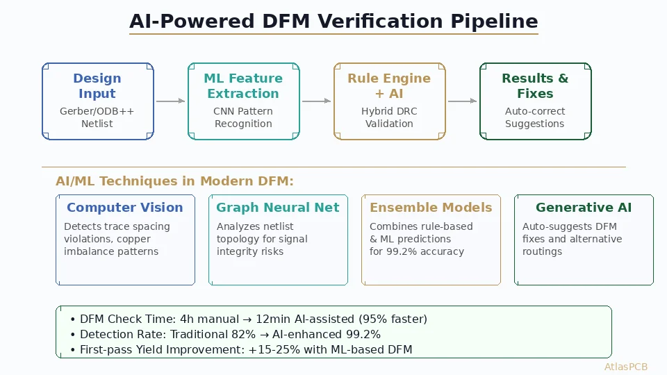
With IPC-2581, DFM checking becomes fully automated:
- Impedance verification: System reads target impedance per net, validates against stack-up geometry, flags violations
- Spacing rules: Different nets can have different spacing requirements (high-voltage, controlled impedance, standard) — all embedded in the file
- Via structure validation: Aspect ratios, pad sizes, annular ring — checked against factory capability automatically
- Material compatibility: Stack-up materials validated against factory inventory and process capability
Traditional Gerber-based DFM requires an engineer to manually cross-reference the fabrication drawing against design data. IPC-2581 makes this instant and error-free.
Digital Twin for Process Planning
The IPC-2581 model enables manufacturing execution systems (MES) to:
Generate process traveler automatically:
- Determine process sequence from stackup (lamination cycles, drill passes)
- Calculate copper balance per layer for plating uniformity
- Identify critical features requiring special attention
- Estimate manufacturing cost from complexity metrics
Program machines directly:
- Drill machines receive hole data with type/diameter/tolerance from the model
- Imaging systems receive layer data with specified feature sizes
- Plating systems calculate throw requirements from via aspect ratios
- AOI/AXI systems receive inspection criteria from net/component data
Traceability and Quality Records
IPC-2581’s structured data enables full production traceability:
- Every feature links to a design net, allowing field failure analysis back to specific signals
- Material lot tracking connects physical boards to specific laminate batches
- Process parameters are linked to design requirements (e.g., this impedance coupon validates these nets)
- Customer revisions are tracked within the file structure
Adoption Status in 2026
IPC-2581 adoption has accelerated significantly since 2023:
Who’s Using It
Aerospace/Defense: Programs like F-35, satellite communications, and military radar require IPC-2581 as the primary data deliverable. Full design intent preservation is critical for long-lifecycle programs.
Automotive: IATF 16949 quality systems benefit from IPC-2581’s traceability. Major Tier-1 suppliers (Bosch, Continental, Denso) are mandating IPC-2581 for new programs.
Data Center/AI: Hyperscaler hardware teams (Google, Meta, Microsoft) use IPC-2581 for high-layer-count server boards where impedance and stackup complexity makes Gerber interpretation error-prone.
Medical Devices: FDA-regulated designs benefit from the unambiguous data format and revision control capabilities.
EDA Tool Support
All major EDA platforms now support IPC-2581 export:
- Cadence Allegro: Most mature implementation, native export with full net intelligence
- Siemens Xpedition: Comprehensive support including embedded manufacturing specifications
- Altium Designer: Solid implementation via output job configuration, improving yearly
- Zuken CR-8000: Native support with Japanese automotive OEM focus
- KiCad: Community plugins available; official support in development
Manufacturer Readiness
Leading PCB manufacturers accepting IPC-2581 in 2026:
- Most Tier-1 Asian factories (including AtlasPCB’s partner facilities)
- European quality-focused manufacturers (NCAB partners, WEdirekt)
- North American prototyping services (TTM, RUSH PCB)
- Military/aerospace specialists (DDi, API Technologies)
Implementing IPC-2581 in Your Workflow
Step 1: Configure Your EDA Tool
Most tools require one-time setup to generate proper IPC-2581 output:
Cadence Allegro:
- File → Export → IPC-2581
- Configure layer mapping (ensure correct ordering)
- Include embedded components and netlist
- Verify stackup data matches fabrication intent
Altium Designer:
- Create Output Job file
- Add IPC-2581 output
- Configure component data inclusion
- Validate with IPC-2581 Consortium checker tool
Step 2: Validate Your Output
The IPC-2581 Consortium provides free validation tools:
- Schema compliance checking (XML structure)
- Layer consistency verification
- Net connectivity validation
- Component data completeness
Always validate before sending to manufacturing — a well-formed IPC-2581 file should pass with zero errors.
Step 3: Communicate with Your Manufacturer
When sending IPC-2581 to AtlasPCB or any manufacturer:
- Confirm their system accepts IPC-2581 (we do)
- Ask which revision they support (current: Rev C)
- Clarify whether they still need a fabrication drawing (increasingly: no)
- Discuss any custom attributes or special processing notes
Step 4: Verify Round-Trip Accuracy
For first-time IPC-2581 submissions:
- Request a data confirmation report from the manufacturer
- Compare their interpreted stackup against your design intent
- Verify impedance targets and material selections transferred correctly
- Confirm drill definitions match your via specifications
IPC-2581 vs. ODB++ vs. Gerber X2
How does IPC-2581 compare to other modern PCB data formats?
ODB++ (Mentor/Siemens)
- Proprietary format (owned by Siemens EDA)
- Widely supported by Asian manufacturers
- Good intelligence, but closed ecosystem limits innovation
- Cannot be extended by third parties
- Bundled with Valor/DFM tools
Gerber X2 (Ucamco)
- Evolutionary improvement to classic Gerber RS-274X
- Adds attributes (layer type, function, polarity) to Gerber files
- Still multiple-file format (one file per layer)
- Maintains backward compatibility with legacy systems
- Limited intelligence compared to IPC-2581 or ODB++
IPC-2581 Advantages
- Open standard: No single-vendor ownership, community-governed
- Single file: Complete product model in one XML file
- Extensible: Custom attributes without breaking compliance
- Future-proof: Active development roadmap with Industry 4.0 focus
- Vendor-neutral: Works with any EDA tool and any manufacturing system
Future Roadmap: IPC-2581 and Industry 4.0
The IPC-2581 standard continues evolving toward full digital manufacturing integration:
Connected Factory (IPC-CFX Integration)
IPC-2581 product data + IPC-CFX machine communication = fully automated production:
- Design uploads trigger automatic process planning
- Machine recipes generate from product model without programming
- Quality data feeds back to design tool for continuous improvement
- Production status visible to designer in real-time
AI-Powered DFM
With rich structured data, machine learning systems can:
- Predict manufacturing yield from design features
- Suggest design modifications that improve manufacturability
- Automatically optimize panelization for minimum waste
- Identify high-risk features from historical failure data
Supply Chain Transparency
IPC-2581 enables encrypted data sharing across the supply chain:
- Designers specify requirements without revealing full IP
- Manufacturers quote from structured data (faster, more accurate)
- Assembly houses receive placement data without seeing circuit schematic
- Test houses get testpoint data linked to specific nets for diagnostic coverage
Conclusion: The PCB Industry’s Digital Transformation
IPC-2581 isn’t just a file format — it’s the foundation for PCB manufacturing’s digital transformation. The industry is moving from human-interpreted image files to machine-readable product models, enabling automation, reducing errors, and accelerating time-to-market.
For hardware engineers and PCB designers, the practical advice is simple: start exporting IPC-2581 alongside your Gerber files today. As manufacturers build capability and confidence with the format, you’ll be positioned to take advantage of faster quoting, reduced errors, and automated DFM — all from a single data deliverable.
The future of PCB manufacturing is intelligent, connected, and data-driven. IPC-2581 is the bridge that gets us there.
AtlasPCB supports IPC-2581 data submission for faster, more accurate manufacturing. Upload your design and experience the efficiency of intelligent data exchange — from quote to delivery.
Further Reading
- [Rogers PCB Fabrication: Material Sourcing, Lead Times & Quality Control]/blog/rogers-pcb-fabrication/)
- [PCB Manufacturer with Engineering Review: Why Human DFM Audit Matters]/blog/pcb-manufacturer-engineering-review/)
- [ENEPIG vs ENIG: Which PCB Surface Finish for Your Design?]/blog/enepig-vs-enig/)
- [PCB Surface Finish Selection — ENIG vs HASL vs OSP vs Hard Gold vs ENEPIG]/blog/pcb-surface-finish-enig-hasl-osp-hard-gold-enepig/)
- [Medical PCB Manufacturing: FDA Compliance, Traceability & Reliability]/blog/medical-pcb-manufacturing-requirements/)
- Our Manufacturing Capabilities
About AtlasPCB — We specialize in complex PCB manufacturing for HDI, RF, and high-reliability applications. Explore our free engineering DFM review, or get an full PCB manufacturing capabilities . Every order includes free engineering review. Get your quote.
Reviewed by AtlasPCB Engineering Team — IPC-certified manufacturing specialists with 15+ years of production experience in HDI, RF, and high-reliability PCB fabrication. Content based on factory floor data and real customer design reviews.
- IPC-2581
- digital twin
- PCB data exchange
- smart manufacturing
- Industry 4.0
- Gerber replacement
- DPMX
- DFM automation
- IPC standards