· AtlasPCB Engineering · Engineering · 8 min read
ENEPIG vs ENIG Surface Finish: Complete Comparison for Wire Bonding, Solderability, and Long-Term Reliability
Compare ENEPIG and ENIG PCB surface finishes for wire bonding, BGA soldering, and press-fit applications. Covers nickel corrosion risks, gold thickness specifications, palladium's role, cost analysis, and selection guidelines for aerospace, automotive, and consumer electronics.
Introduction: Surface Finish as a Reliability Decision
PCB surface finish is not a cosmetic choice — it’s a reliability engineering decision that affects solder joint strength, wire bond integrity, contact resistance, shelf life, and long-term corrosion performance. The wrong surface finish selection can cause field failures years after assembly, making it one of the most consequential DFM decisions in electronics manufacturing.
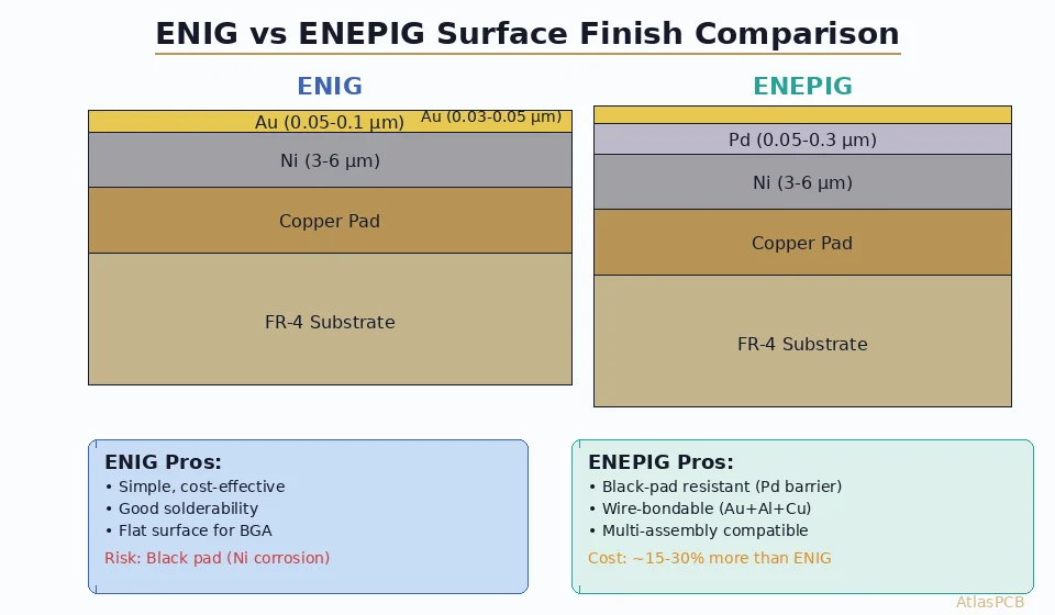
Among the advanced surface finishes, ENIG (Electroless Nickel Immersion Gold) and ENEPIG (Electroless Nickel Electroless Palladium Immersion Gold) represent the two dominant options for high-reliability applications. Both provide flat, coplanar surfaces ideal for fine-pitch BGA and wire bonding, but they differ significantly in one critical area: the interface between nickel and gold.
This guide provides a complete engineering comparison to help you select the right finish for your application requirements.
Understanding the Layer Structure
ENIG: Three-Layer System
┌─────────────────────────────┐
│  Immersion Gold (1-3 µin)   │  ← Solderable surface, protects Ni
├─────────────────────────────┤
│  Electroless Nickel (120-240 µin) │  ← Barrier layer, structural
├─────────────────────────────┤
│  Copper Pad                 │  ← PCB base metal
└─────────────────────────────┘Process: Copper activation → electroless nickel (EN) deposition → immersion gold (IG) displacement reaction.
The immersion gold step is a displacement reaction: gold ions in solution displace nickel atoms from the surface. This inherently attacks the nickel — which is both the mechanism that deposits gold AND the source of black pad risk.
ENEPIG: Four-Layer System
┌─────────────────────────────┐
│  Immersion Gold (1-3 µin)   │  ← Protects Pd, provides solderability
├─────────────────────────────┤
│  Electroless Palladium (4-10 µin) │  ← Wire bond surface, Ni protector
├─────────────────────────────┤
│  Electroless Nickel (120-240 µin) │  ← Barrier layer, structural
├─────────────────────────────┤
│  Copper Pad                 │  ← PCB base metal
└─────────────────────────────┘Process: Copper activation → electroless nickel → electroless palladium → immersion gold.
The palladium layer is deposited by autocatalytic reduction (not displacement), meaning it deposits onto nickel without attacking it. The subsequent immersion gold step attacks the palladium — but palladium is far more corrosion-resistant than nickel, so no “black pad” equivalent occurs.
The Black Pad Problem: ENIG’s Achilles Heel
What Is Black Pad?
Black pad (formally: electroless nickel/immersion gold interfacial fracture) is a latent defect where the nickel-gold interface is compromised during ENIG processing. The affected pads appear normal visually but contain a microscopically corroded nickel surface beneath the gold.
Failure mechanism:
- During immersion gold deposition, gold ions aggressively attack nickel grain boundaries
- Phosphorus-rich nickel phases corrode preferentially (hyperactive corrosion)
- A thin layer of nickel corrosion products (dark/black in color) forms at the interface
- Solder wets the gold but cannot form a reliable intermetallic with the corroded nickel
- Joint appears formed but is mechanically weak — fails under thermal cycling or mechanical stress
Black Pad Detection Challenges
Black pad is insidious because:
- Visual inspection cannot detect it (gold covers the defect)
- X-ray inspection cannot detect it (too thin)
- Standard ICT/functional test may pass initially
- Failure occurs weeks to months after assembly under thermal cycling
- Only destructive cross-sectioning or specialized SEM/EDX analysis reveals it
Risk Factors
Black pad occurrence correlates with:
- Nickel phosphorus content: >10% phosphorus increases risk
- Gold bath age: Aged baths with accumulated nickel contamination
- Pad geometry: Large pads with high immersion time
- Bath temperature: Higher temperatures increase corrosion rate
- Process control: Tight EN process window critical (pH, temperature, loading)
ENEPIG’s Solution
ENEPIG eliminates black pad by inserting a palladium barrier between nickel and gold:
- Palladium deposits autocatalytically onto nickel (no displacement/corrosion)
- Gold subsequently attacks palladium, not nickel
- Palladium is much more noble than nickel — minimal interface degradation
- Even if palladium is slightly attacked, it doesn’t produce the brittle corrosion products that cause black pad
Wire Bonding Performance
Gold Wire Bonding
| Parameter | ENIG | ENEPIG | Electrolytic Hard Gold |
|---|---|---|---|
| Bond reliability | Marginal | Excellent | Excellent |
| Ball bond shear | Variable (black pad risk) | >15 gf typical | >15 gf typical |
| Stitch bond | Poor (insufficient Au thickness) | Good | Excellent |
| Process window | Narrow | Wide | Wide |
| Recommended? | No | Yes | Yes (but higher cost) |
Aluminum Wire Bonding
| Parameter | ENIG | ENEPIG |
|---|---|---|
| Wedge bond | Not suitable | Excellent |
| Bond mechanism | Au-Al intermetallic (Kirkendall voids) | Pd serves as bond surface |
| Long-term reliability | Poor (purple plague risk) | Very good |
| Recommended? | No | Yes |
ENEPIG’s unique advantage: It supports BOTH gold and aluminum wire bonding on the same board. This enables mixed-technology assemblies where some die use gold wire bonds (standard IC packaging) while others use aluminum (power devices, automotive-grade parts).
Wire Bonding PCB Projects?
AtlasPCB offers ENEPIG, ENIG, and selective hard gold plating with IPC Class 3 process control. Free DFM review for wire bonding designs.
Request ENEPIG Quote →Solderability Comparison
BGA/CSP Assembly
Both ENIG and ENEPIG provide excellent solderability for BGA assembly:
- Coplanarity: Both provide flat surfaces ideal for fine-pitch BGA (≤0.4mm pitch)
- Wetting: Both wet well with SAC305 and SnBi solder pastes
- IMC formation: ENIG forms Ni₃Sn₄ intermetallic; ENEPIG forms (Ni,Pd)₃Sn₄ + PdSn₄
- Joint strength: ENEPIG typically shows 10-15% higher BGA pull/shear strength
Multiple Reflow Cycles
Surface finish stability through multiple thermal excursions:
| Condition | ENIG | ENEPIG |
|---|---|---|
| After 1 reflow | Excellent | Excellent |
| After 3 reflows | Good | Excellent |
| After 5 reflows | Marginal (Ni oxidation risk) | Good |
| After 6+ reflows | Not recommended | Acceptable for double-sided SMT + rework |
Shelf Life
| Condition | ENIG | ENEPIG |
|---|---|---|
| Factory environment | 12 months | 12+ months |
| Standard packaging | 6-12 months | 12-18 months |
| Long-term storage | Risk of Ni diffusion through thin Au | Pd barrier prevents Ni migration |
Press-Fit Connector Compatibility
Press-fit connectors require surface finishes that:
- Provide low and stable contact resistance
- Withstand the mechanical stress of pin insertion
- Don’t generate debris that could cause shorts
ENIG: Adequate for press-fit. Nickel hardness (500-700 HV) provides mechanical durability. Thin gold prevents galling.
ENEPIG: Excellent for press-fit. Palladium adds additional hardness and lubricity. Contact resistance stability is superior over temperature cycling.
This makes ENEPIG the ideal choice for mixed-technology boards combining SMT, wire bonding, AND press-fit connectors on the same PCB — a common requirement in automotive ECUs and telecommunications equipment.
Process Control and Quality Indicators
ENIG Quality Metrics
| Parameter | Specification | Test Method |
|---|---|---|
| Nickel thickness | 120-240 µin (3-6 µm) | XRF |
| Gold thickness | 1.5-3.0 µin (0.04-0.08 µm) | XRF |
| Nickel phosphorus | 7-10% (mid-phos) | Chemical analysis |
| Black pad risk | <0.1% affected pads | SEM cross-section (destructive) |
| Solderability | >95% wetting within 3s | J-STD-003 |
ENEPIG Quality Metrics
| Parameter | Specification | Test Method |
|---|---|---|
| Nickel thickness | 120-240 µin (3-6 µm) | XRF |
| Palladium thickness | 4-10 µin (0.1-0.25 µm) | XRF |
| Gold thickness | 1-3 µin (0.03-0.08 µm) | XRF |
| Nickel phosphorus | 7-10% (mid-phos) | Chemical analysis |
| Wire bond pull | >4 gf (25µm Au wire) | MIL-STD-883 |
| Solderability | >95% wetting within 2s | J-STD-003 |
Cost Analysis
Per-Board Cost Comparison (100×100mm, 4-layer)
| Finish | Process Cost | Total Add per Board | Notes |
|---|---|---|---|
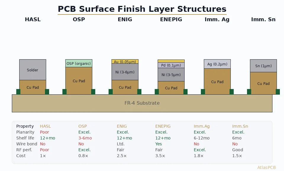
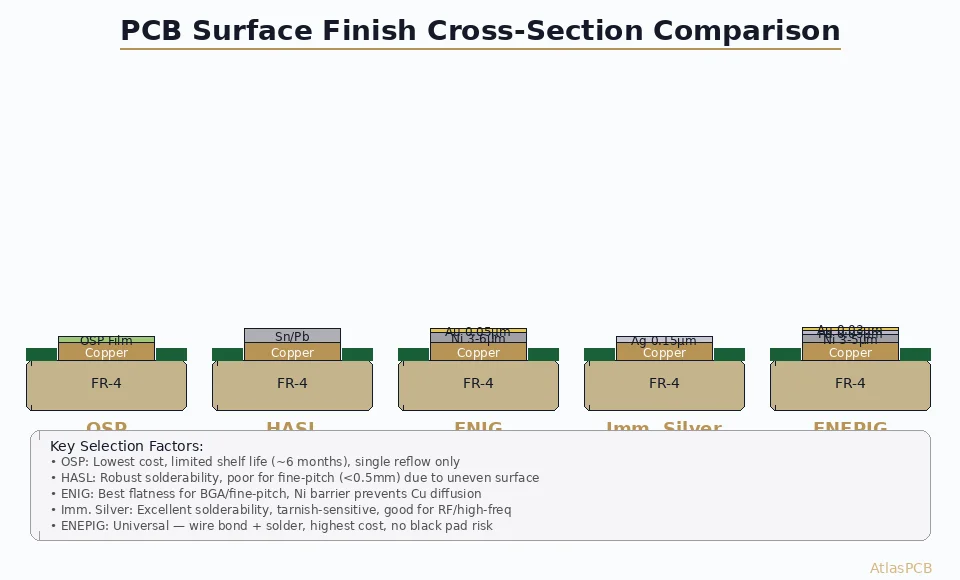
| HASL | Lowest | +$0.10-0.20 | Not flat enough for <0.5mm pitch |
| OSP | Low | +$0.05-0.15 | Short shelf life, no wire bond |
| ENIG | Medium | +$0.50-0.80 | Black pad risk |
| ENEPIG | Medium-High | +$0.65-1.10 | Universal finish |
| Hard Gold (selective) | High | +$1.50-3.00 | Only for specific pads |
When ENEPIG’s Premium Is Justified
The 20-35% cost premium over ENIG is justified when:
- Wire bonding is required (COB, SiP, hybrid assemblies)
- Multiple assembly processes on same board (SMT + wire bond + press-fit)
- Long shelf life needed (spare parts, inventory management)
- Zero-defect requirement (aerospace, medical implants, automotive safety)
- High reflow count (complex assemblies with 4+ thermal cycles)
When ENIG Is Sufficient
ENIG remains the right choice when:
- Assembly is SMT-only (no wire bonding)
- Black pad risk is managed through supplier qualification
- Shelf life requirement is <12 months
- Cost optimization is priority over maximum reliability margin
Application Selection Guide
Automotive Electronics (ISO 26262)
Recommended: ENEPIG
- Wire bonding common in power modules and sensor ICs
- Zero-defect requirement for ASIL-C/D systems
- Extended temperature range (-40°C to +150°C) stresses interfaces
- Long production life (15+ year vehicle lifecycle requires spare parts)
Aerospace and Defense (MIL-PRF-31032)
Recommended: ENEPIG or selective hard gold
- Wire bonding for hybrid assemblies and MCMs
- Extreme reliability requirements (Class 3 per [IPC-A-600]/blog/ipc-a-600-class-2-vs-class-3-pcb-acceptability-en/))
- Conformal coating compatibility (both finishes compatible)
- Long storage life for strategic reserves
Consumer Electronics (Cost-Optimized)
Recommended: ENIG (unless wire bonding present)
- High volume drives need for cost optimization
- Automated SMT assembly doesn’t require wire bonding capability
- 6-12 month shelf life adequate for fast-turning inventory
- Accept managed black pad risk with qualified suppliers
Medical Devices (ISO 13485)
Recommended: ENEPIG
- Implantable devices require maximum reliability
- Mixed assemblies common (sensors + ICs + connectors)
- Traceability requirements align with ENEPIG’s broader process window
- Long shelf life for sterilized medical inventory
Telecommunications (Carrier-Grade)
Recommended: ENEPIG
- Press-fit backplane connectors + SMT + wire bonding on same board
- 20+ year field life expectation
- Thermal cycling from outdoor installations
- [RF performance]/blog/rf-pcb-rogers-vs-ptfe-material-selection-5g-en/) requirements demand stable contact resistance
IPC Standards for Surface Finish
Relevant standards governing ENIG and ENEPIG:
- IPC-4552A: ENIG performance specification (revision A adds tighter process control)
- IPC-4556: ENEPIG performance specification
- IPC-J-STD-003: Solderability testing
- IPC-4553: Immersion Silver specification (alternative to consider)
Ensure your fabricator is certified to the latest revision and performs in-process monitoring of bath chemistry, deposition rate, and thickness uniformity.
Conclusion: When in Doubt, Choose ENEPIG
If your design has any chance of needing wire bonding, mixed-technology assembly, or maximum reliability margin, ENEPIG is the safer choice. Its 20-35% premium over ENIG buys elimination of black pad risk, wire bonding capability, and longer shelf life — insurance against field failures that cost far more than the upfront material premium.
For high-volume consumer SMT-only assemblies where cost optimization is paramount and black pad risk is managed through supplier qualification, ENIG remains a cost-effective choice.
Need guidance on surface finish selection? AtlasPCB’s engineers evaluate your assembly requirements, operating environment, and reliability targets to recommend the optimal finish. We offer ENIG, ENEPIG, HASL, OSP, immersion tin, immersion silver, and selective hard gold.
Discuss Your Surface Finish Requirements → | Compare All Finish Options →
Further Reading
- [PCB Surface Finish Comparison: OSP vs HASL vs Immersion Silver vs ENIG for Assembly Reliability]/blog/pcb-surface-finish-osp-hasl-enig-immersion-silver-comparison/)
- [ENEPIG vs ENIG: Which PCB Surface Finish for Your Design?]/blog/enepig-vs-enig/)
- [PCB Surface Finish Selection — ENIG vs HASL vs OSP vs Hard Gold vs ENEPIG]/blog/pcb-surface-finish-enig-hasl-osp-hard-gold-enepig/)
- [mmWave PCB Material Selection: Rogers vs Megtron vs LCP for 5G and 6G Applications]/blog/mmwave-pcb-material-selection-rogers-megtron-lcp-5g-6g/)
- [Rogers PCB Fabrication: Material Sourcing, Lead Times & Quality Control]/blog/rogers-pcb-fabrication/)
- Rigid PCB Manufacturing
About AtlasPCB — We specialize in complex PCB manufacturing for HDI, RF, and high-reliability applications. Explore our RF and high-frequency PCB services, or get an full PCB manufacturing capabilities . Every order includes free engineering review. Get your quote.
Reviewed by AtlasPCB Engineering Team — IPC-certified manufacturing specialists with 15+ years of production experience in HDI, RF, and high-reliability PCB fabrication. Content based on factory floor data and real customer design reviews.
- ENEPIG
- ENIG
- surface finish
- wire bonding
- PCB plating
- black pad
- gold finger