· AtlasPCB Engineering · Engineering · 12 min read
IPC-2581 vs Gerber: The Future of PCB Data Transfer
An in-depth comparison of IPC-2581 and Gerber formats for PCB manufacturing data exchange. Learn why the industry is moving toward intelligent, single-file data transfer and what it means for your design workflow.
IPC-2581 vs Gerber: The Future of PCB Data Transfer
Every PCB ever manufactured started as a data package sent from a designer to a fabricator. For decades, that package has been a collection of Gerber files — a format born in 1980 from the needs of photoplotter hardware that no longer exists. Alongside those Gerbers, engineers send drill files (Excellon format), netlists (IPC-D-356), stackup drawings (PDFs), fabrication notes (more PDFs), impedance requirements (yet more PDFs), and bill-of-materials spreadsheets. A complete manufacturing data package for a complex 12-layer HDI board might contain 30–50 individual files, many of which duplicate or contradict each other.
This fragmented approach has persisted not because it’s good, but because it’s universal. Every EDA tool exports Gerber. Every fabricator imports Gerber. The infrastructure is entrenched.
IPC-2581 represents a fundamentally different approach: one intelligent file containing everything a fabricator and assembler need. No ambiguity. No missing files. No conflicting information between a Gerber layer and a fabrication drawing. The question is no longer whether IPC-2581 is better — it clearly is — but whether the industry’s adoption has reached the point where you can confidently use it today.
The Gerber Format: Legacy and Limitations
A Brief History
The Gerber format was created by Gerber Systems Corporation (later acquired by Barco) to drive vector photoplotter machines. The original RS-274-D format was a simple command language for moving a light aperture across photographic film — essentially a pen-plotter language for light.
The current standard, Gerber RS-274X (Extended Gerber), added embedded aperture definitions and macro capabilities, eliminating the separate aperture table files that plagued early workflows. In 2014, Ucamco (Barco’s successor) introduced Gerber X2, adding structured metadata attributes to the format — layer type identification, file function descriptors, and component information.
Despite these improvements, Gerber remains fundamentally a 2D image format. Each file describes what copper, soldermask, silkscreen, or paste looks like on one layer. It doesn’t know what those shapes mean electrically.
What Gerber Cannot Do
No embedded netlist. A Gerber file shows copper pads and traces but has no concept of which ones are connected. If pad A on layer 1 should connect to pad B on layer 8 through a via, the Gerber files contain the shapes for all three elements but no information linking them. The fabricator must run a separate netlist comparison (using an IPC-D-356 or ODB++ netlist) to verify connectivity.
No material intelligence. Gerber files don’t specify what material each layer should use. Whether the dielectric between layers 1 and 2 should be Rogers RO4350B or standard FR4 is communicated separately — typically in a PDF fabrication drawing that may or may not match the actual stackup embedded in the designer’s EDA tool.
No impedance context. When a fabricator sees a 5-mil trace in a Gerber file, they don’t know whether it’s a 50Ω controlled impedance line or a non-critical digital signal. Impedance requirements are communicated through separate documents, and misinterpretation is a common source of manufacturing defects.
No component or assembly data. Gerber files for paste layers and silkscreen provide shapes, but which component goes where — reference designators, BOM entries, placement coordinates — requires additional files (pick-and-place data, BOM spreadsheets, assembly drawings).
File coordination problems. A 10-layer board generates 20+ Gerber files (copper layers, soldermask layers, paste layers, silkscreen layers, outline, drill files, netlist file). File naming conventions vary between EDA tools. A fabricator receiving a ZIP file must manually identify which file corresponds to which layer — a process prone to human error that has caused countless manufacturing mistakes.
For guidance on correctly preparing your Gerber data package, see our [Gerber files guide]/blog/pcb-gerber-files-guide/).
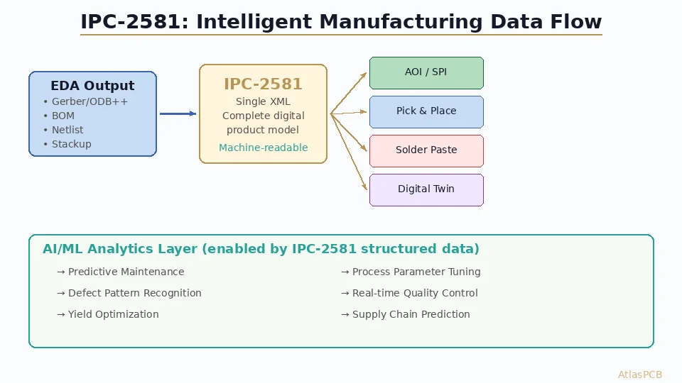
IPC-2581: One File, Complete Data
What It Contains
IPC-2581 is an XML-based format defined by the IPC (Association Connecting Electronics Industries). The current revision is IPC-2581C (released 2023), building on the original 2004 specification. It encapsulates:
- Complete layer imagery — all copper, mask, and silkscreen artwork in a single file
- Stackup definition — layer order, materials, thicknesses, dielectric properties with specific material callouts
- Netlist with connectivity — full net-to-pad connectivity map, enabling the fabricator to verify electrical correctness without a separate IPC-D-356 file
- Component data — reference designators, package types, placement coordinates, and rotation — sufficient for assembly without a separate pick-and-place file
- Bill of materials — component descriptions, manufacturer part numbers, and quantities
- Fabrication instructions — impedance requirements tied to specific nets, drill specifications, surface finish, tolerances, and special processing notes
- Design intent — which features are critical dimensions, where controlled impedance is required, and what tolerances apply
The Single-File Advantage
Consider the data flow for a typical 8-layer HDI board:
Traditional Gerber package (18+ files):
- 8 copper layer Gerbers
- 2 soldermask Gerbers
- 2 silkscreen Gerbers
- 2 paste layer Gerbers
- 1 board outline Gerber
- 1-2 drill files (plated + non-plated)
- 1 IPC-D-356 netlist
- 1 fabrication drawing (PDF)
- 1 stackup document (PDF or spreadsheet)
- 1 impedance specification document
- Pick-and-place file
- BOM spreadsheet
- Assembly drawing (PDF)
- README or fabrication notes
IPC-2581 package: 1 file.
That single file is machine-readable, self-validating, and unambiguous. There’s no possibility of the stackup PDF contradicting the actual layer structure, because both are encoded in the same data model.
Data Integrity and Validation
IPC-2581 files are structured XML with a defined schema. This means:
- Automated validation — CAM software can programmatically verify that the file is complete and internally consistent before processing begins
- No interpretation required — layer assignments, material specifications, and impedance requirements are explicitly stated, not inferred from file names or PDF annotations
- Version tracking — the file format supports revision metadata, making it clear which version of the design is being manufactured
- DFM integration — because the file contains netlist and stackup data, DFM analysis can run automatically upon import, flagging issues immediately
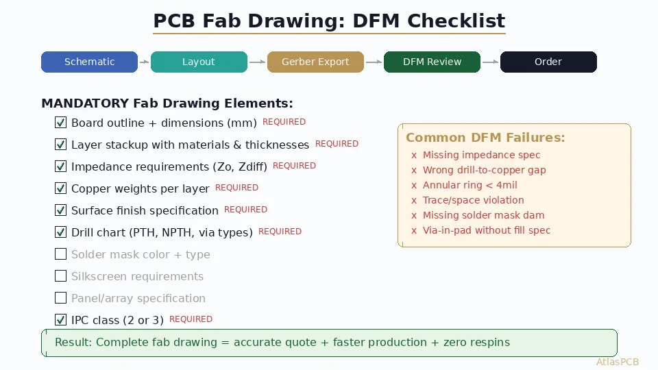
For best practices on preparing manufacturing-ready designs, see our [DFM checklist]/blog/pcb-dfm-checklist/).

ODB++: The Other Contender
Any discussion of PCB data formats must address ODB++, the proprietary format developed by Valor (now part of Siemens EDA). ODB++ has been widely adopted by fabricators since the early 2000s and offers many of the same benefits as IPC-2581 — structured data, embedded netlist, component information, and stackup definition.
ODB++ vs IPC-2581: Key Differences
| Feature | ODB++ | IPC-2581 |
|---|---|---|
| Standard type | Proprietary (Siemens) | Open (IPC) |
| File structure | Directory-based (tarball) | Single XML file |
| Netlist | Yes | Yes |
| Stackup | Yes | Yes |
| Component data | Yes | Yes |
| Impedance specs | Limited | Yes (net-level) |
| Material callouts | Limited | Yes (per-layer) |
| Schema validation | Custom | XML Schema (XSD) |
| Licensing | Siemens license terms | Free, open standard |
| EDA support | Siemens tools native; others via export | Cadence, Siemens, Altium, others |
| Fabricator adoption | High (especially large shops) | Growing rapidly |
The fundamental philosophical difference: ODB++ is controlled by a single company, while IPC-2581 is governed by an industry consortium. For organizations concerned about vendor lock-in or long-term data archival, IPC-2581’s open standard status is a significant advantage.
Practical Reality in 2026
In practice, many large fabricators accept all three formats (Gerber, ODB++, and IPC-2581) and convert internally to their preferred CAM system format. The downstream manufacturing processes don’t care which format arrived — they care that the CAM data is correct.
The real benefit of IPC-2581 and ODB++ over Gerber materializes at the data import and validation stage. When a fabricator receives Gerber files, an experienced CAM engineer spends 30–90 minutes manually reviewing, organizing, and configuring the data. With IPC-2581 or ODB++, this import process can be largely automated, reducing NPI (new product introduction) time and the risk of setup errors.
EDA Tool Support in 2026
IPC-2581 export capability is now available in all major EDA platforms:
- Cadence Allegro/OrCAD — native IPC-2581C export since version 17.4, mature and widely used
- Siemens Xpedition — full IPC-2581 support (alongside native ODB++ export)
- Altium Designer — IPC-2581 export added in version 23.x, steadily improving with each release
- Zuken CR-8000 — native IPC-2581 support
- KiCad — IPC-2581 export available since version 8.0 (2024), rapidly maturing
The export process in most tools is straightforward — typically a single menu option that generates the complete IPC-2581 file from your design database. No manual configuration of layer mappings or file naming is required, which eliminates an entire category of human error inherent in Gerber export.
Export Best Practices
When exporting IPC-2581 from your EDA tool:
- Verify your stackup is fully defined in the EDA tool before export — IPC-2581 will faithfully reproduce whatever is configured, including errors
- Ensure net names are clean — cryptic auto-generated net names (N$0001) will propagate into the manufacturing data; meaningful names improve communication
- Include impedance requirements in the design constraints — IPC-2581 can carry this information directly to the fabricator
- Export both IPC-2581 and Gerber during the transition period — this gives fabricators a fallback while they upgrade their import capabilities
- Validate the export using the IPC-2581 Consortium’s free validation tools before sending to fabrication
Fabricator Adoption: Where Are We?
Fabricator adoption of IPC-2581 has followed a predictable pattern: large, technologically advanced shops led the way, followed by mid-tier fabricators, with smaller regional shops lagging behind.
Current Landscape (2026)
- Tier 1 fabricators (TTM, AT&S, Schweizer, Unimicron) — full IPC-2581 import capability, actively encouraging customers to switch
- Advanced mid-tier fabricators — most can import IPC-2581; some prefer it for complex designs (HDI, flex-rigid, RF)
- Standard mid-tier fabricators — IPC-2581 acceptance growing; some still convert to Gerber internally
- Small/regional fabricators — limited adoption; Gerber remains the primary format
The adoption gap correlates directly with CAM software investment. Fabricators using modern CAM systems (Ucamco Integr8tor, Siemens Valor, Frontline InCAM) have IPC-2581 import built into their workflow. Those using older or lower-cost CAM tools may not yet support the format.
What This Means for You
If you’re sending designs to a major fabricator or to a manufacturer that advertises IPC-2581 support, use it. The data transfer will be cleaner, faster, and less error-prone.
If you’re working with a small local shop or a budget overseas fabricator, check first. Sending IPC-2581 to a shop that can’t import it wastes time for both parties.
The safest approach today: export IPC-2581 as your primary format and include a Gerber package as backup. This future-proofs your workflow while maintaining backward compatibility.
Practical Benefits of Switching
Reduced NPI Time
When a fabricator receives IPC-2581 data, the automated import can reduce CAM setup time from 1–2 hours to 15–30 minutes. For prototype orders where NPI time directly impacts lead time, this can shave a day off your delivery schedule.
Fewer Engineering Queries
A significant portion of fabricator engineering queries (“Which layer is the board outline?” “Is this impedance spec for single-ended or differential?” “What material should be used between layers 3 and 4?”) arise from ambiguities in Gerber data packages. IPC-2581 eliminates most of these by providing explicit, machine-readable answers.
Automatic DFM Analysis
With netlist-aware data, fabricators can run more sophisticated DFM checks. Instead of just checking copper-to-copper clearances (which is all Gerber enables), IPC-2581-aware DFM tools can verify:
- Net-to-net spacing violations (different nets may require different clearances based on voltage class)
- Impedance-critical trace geometry errors
- Via-to-pad net assignments
- Component-to-board-edge clearances with component height awareness
Supply Chain Integration
IPC-2581’s embedded BOM and component data enable tighter integration between fabrication and assembly. A contract manufacturer receiving IPC-2581 data can feed it directly into their placement machines, component procurement systems, and inspection equipment — one file from design through final assembly.
Challenges and Limitations
File Size
IPC-2581 files can be large. A complex 20-layer design might generate a 200–500 MB XML file, compared to a 20–50 MB Gerber ZIP package. This is mostly a storage and transfer consideration — modern internet speeds and cloud-based quoting systems handle these file sizes without difficulty, but email attachments may be problematic.
Learning Curve
Engineers accustomed to reviewing Gerber files in a viewer (GerbView, ViewMate, Ucamco Reference Gerber Viewer) need new tools for IPC-2581. Most CAM platforms include IPC-2581 viewers, and standalone options exist, but the ecosystem is less mature than the Gerber viewer landscape.
Edge Cases
Some advanced manufacturing features — embedded components, flex-rigid transition zones, non-standard materials — may not be fully described by the current IPC-2581C schema. The specification continues to evolve, but if your design uses cutting-edge technologies, verify that your specific requirements can be expressed in the format before committing to IPC-2581 exclusively.
The Path Forward
The transition from Gerber to IPC-2581 is not a sudden switch — it’s a gradual migration that’s been underway for years and is now reaching a tipping point. The analogy to the STEP file adoption in mechanical CAD is instructive: STEP didn’t kill IGES overnight, but today STEP is the clear default for 3D model exchange, and IGES survives only in legacy workflows.
IPC-2581 is on the same trajectory. Within the next 3–5 years, it’s reasonable to expect that:
- All Tier 1 and Tier 2 fabricators will prefer IPC-2581 input
- EDA tools will default to IPC-2581 export alongside Gerber
- Automated quoting systems will parse IPC-2581 for instant pricing (something already happening at forward-thinking fabricators)
- New engineers entering the industry will learn IPC-2581 as the primary format
The engineers who adopt IPC-2581 today gain immediate benefits in data quality and NPI efficiency, and they’re building workflow muscle memory that will become essential as the industry completes the transition.
Recommendations
- Start exporting IPC-2581 alongside Gerber — build familiarity with the format and identify any issues in your specific design flow
- Ask your fabricator about IPC-2581 support — their answer tells you a lot about their technological maturity
- Clean up your EDA tool’s design data — IPC-2581 exposes sloppy stackup definitions and unassigned net names that Gerber hides
- Use IPC-2581 for new designs, Gerber for legacy — don’t try to retroactively convert old designs, but make the switch for new projects
- Provide both formats during the transition period to avoid surprises
The era of shipping ZIP files full of cryptically named Gerbers with a PDF that says “please read carefully” is ending. IPC-2581 represents what PCB data transfer should have always been: one file, complete data, zero ambiguity.
Ready to start your project? Upload your Gerbers for a free engineering review, or talk to an engineer about your design requirements.
Further Reading
- [PCB Manufacturer with Engineering Review: Why Human DFM Audit Matters]/blog/pcb-manufacturer-engineering-review/)
- [PCB Panelization and Array Design: V-Score vs Tab Routing, DFM Rules, and Cost Optimization]/blog/pcb-panelization-v-score-tab-routing-dfm-cost-optimization/)
- [Rogers PCB Fabrication: Material Sourcing, Lead Times & Quality Control]/blog/rogers-pcb-fabrication/)
- [阻焊坝设计 — 规则、公差与DFM最佳实践]/blog/pcb-solder-mask-dam-design-rules-dfm/)
- [Aluminum PCB Thermal Design for High-Power LED and Motor Drivers: Material Selection, Stackup, and DFM Guide]/blog/aluminum-pcb-thermal-design-led-motor-driver/)
- Material Options & Capabilities
About AtlasPCB — We specialize in complex PCB manufacturing for HDI, RF, and high-reliability applications. Explore our free engineering DFM review, or get an full PCB manufacturing capabilities . Every order includes free engineering review. Get your quote.
Reviewed by AtlasPCB Engineering Team — IPC-certified manufacturing specialists with 15+ years of production experience in HDI, RF, and high-reliability PCB fabrication. Content based on factory floor data and real customer design reviews.
- ipc-2581
- gerber
- data-transfer
- pcb-manufacturing
- dfm