· AtlasPCB Engineering · Engineering · 6 min read
Rogers vs PTFE Laminates for RF PCB Design: Material Selection Guide for 5G and mmWave Applications
Compare Rogers 4350B, 4003C, RT/duroid, and generic PTFE laminates for RF PCB applications. Covers Dk/Df, thermal stability, processability, and cost considerations for 5G and mmWave designs.
The Material Selection Challenge in RF Design
Choosing the right substrate material is arguably the most consequential decision in RF PCB design. At frequencies above 1 GHz — and especially in the 24–77 GHz mmWave bands driving 5G and automotive radar — the laminate’s dielectric properties directly determine signal loss, impedance accuracy, and overall system performance.
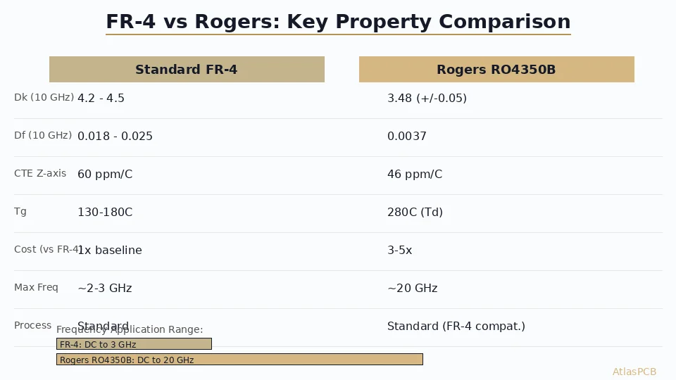
Standard FR-4 becomes impractical above ~3 GHz due to its high dissipation factor (Df ≈ 0.020) and inconsistent dielectric constant (Dk varies with frequency and moisture). Engineers must turn to specialized high-frequency materials, but the options are numerous and the trade-offs non-trivial.
This guide compares the most common RF laminate families — Rogers hydrocarbon ceramics, PTFE-based substrates, and hybrid options — to help you select the right material for your [high-frequency PCB design]/blog/high-frequency-pcb-design-best-practices-en/).
Key Material Properties for RF Applications
Dielectric Constant (Dk)
Dk determines trace geometry for a target impedance. For RF designs, you need:
- Low Dk (2.2–3.5) for wider traces and reduced fabrication sensitivity
- Stable Dk across frequency range (±0.02 or better)
- Stable Dk across temperature (-40°C to +85°C typical operating range)
- Low moisture absorption (water has Dk ≈ 80; absorbed moisture shifts Dk dramatically)
Dissipation Factor (Df)
Df directly translates to insertion loss. At 28 GHz, the difference between Df = 0.0009 (Rogers RT5880) and Df = 0.004 (Rogers 4350B) means approximately 0.5 dB/cm additional loss — critical in antenna feed networks and long transmission lines.
Thermal Properties
- CTE (Coefficient of Thermal Expansion): Z-axis CTE causes via stress during reflow
- Tg (Glass Transition): Must exceed all processing and operating temperatures
- Thermal conductivity: Important for power amplifier boards
Material Comparison: The Major Contenders
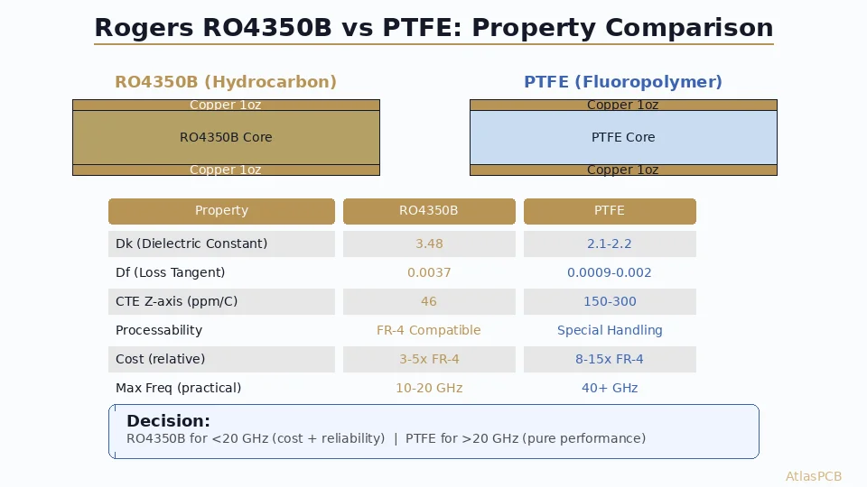
Rogers 4350B (Hydrocarbon Ceramic)
The workhorse of commercial RF design. Not a PTFE material — it uses a thermoset hydrocarbon ceramic-filled resin system.
Properties:
- Dk = 3.48 @ 10 GHz (process specification)
- Df = 0.0037 @ 10 GHz
- CTE (Z): 32 ppm/°C
- Moisture absorption: 0.06%
- Tg: >280°C
Advantages:
- Processes like FR-4 (standard drill, etch, plating)
- No special PTFE handling required
- Excellent Dk tolerance (±0.05 standard)
- Compatible with lead-free assembly
- Widely available, moderate cost
Limitations:
- Higher loss than pure PTFE at >20 GHz
- Not optimal for the lowest-loss mmWave applications
Best for: 5G sub-6 GHz, WiFi 6E/7, GPS, general RF to ~20 GHz
Rogers 4003C (Hydrocarbon Ceramic)
Lower-loss sibling of 4350B with slightly different properties.
Properties:
- Dk = 3.38 @ 10 GHz
- Df = 0.0027 @ 10 GHz
- CTE (Z): 46 ppm/°C
- Moisture absorption: 0.06%
Advantages:
- 27% lower loss than 4350B
- Same ease of processing
- Good for moderate mmWave applications
Limitations:
- Higher Z-axis CTE than 4350B
- Slightly less mechanical stability
Best for: Designs needing better performance than 4350B without PTFE complexity. Learn more in our [Rogers 4003C properties]/blog/rogers-4003c-properties-en/) guide.
Rogers RT/duroid 5880 (PTFE/Glass)
The gold standard for lowest-loss RF substrates.
Properties:
- Dk = 2.20 @ 10 GHz
- Df = 0.0009 @ 10 GHz
- CTE (Z): 237 ppm/°C
- Moisture absorption: 0.02%
Advantages:
- Lowest loss commercially available
- Extremely stable Dk across frequency
- Negligible moisture sensitivity
- Proven in aerospace/defense for decades
Limitations:
- PTFE is soft — requires [special handling procedures]/blog/ptfe-substrate-handling-fabrication-en/)
- High Z-axis CTE makes PTH reliability challenging
- Difficult to bond (requires sodium-naphthalene surface treatment)
- Limited to 2-4 layer constructions typically
- Expensive
Best for: mmWave (28–77 GHz), satellite communications, radar, lowest-loss requirement
Generic PTFE Laminates (Taconic, Arlon, others)
Several manufacturers offer PTFE-based alternatives at lower cost points.
Typical properties (varies by grade):
- Dk = 2.1–2.6
- Df = 0.0010–0.0025
- Processing: similar challenges to RT/duroid
Key consideration: Availability and consistency. Rogers has the largest global distribution network. Generic PTFE may have longer lead times and batch-to-batch variation.
Hybrid Stackups: Combining Materials
For complex designs needing both RF performance and high-density digital routing, [hybrid PCB stackups]/blog/pcb-hybrid-stackup-rogers-fr4-en/) combine RF materials with FR-4:
Example: 6-layer hybrid
- L1 (RF): Rogers 4350B — antenna/transmission lines
- L2 (GND): Copper ground plane
- Core: FR-4 for digital/power layers
- L5 (GND): Copper ground plane
- L6 (RF): Rogers 4350B — if dual-sided RF needed
Challenges:
- CTE mismatch between materials causes warpage
- Registration accuracy between dissimilar materials
- Bonding interface reliability under thermal cycling
- Cost premium of 2–3x vs all-FR-4
Fabrication Considerations
Drilling
PTFE materials are soft and tend to smear during drilling. Standard carbide bits work for Rogers 4350B/4003C, but PTFE substrates may need:
- Specialized drill bits with modified geometry
- Reduced hit count (shorter drill life)
- [Plasma desmear]/blog/pcb-plasma-desmear-process-en/) instead of chemical (permanganate won’t attack PTFE)
Plating
Achieving adhesion to PTFE surfaces requires surface modification:
- Sodium-naphthalene etch (chemical surface activation)
- Plasma treatment (for via walls)
- Modified electroless copper chemistry
Rogers 4350B/4003C avoid these complications — they plate like standard laminates.
Tolerances
RF designs demand tighter impedance control. Typical requirements:
- Dk tolerance: ±0.02–0.05 (material dependent)
- Trace width tolerance: ±0.5 mil (12.5 µm)
- Dielectric thickness tolerance: ±0.5 mil
See our [impedance specification guide]/blog/how-to-specify-impedance-pcb-en/) for detailed tolerance budgeting.
Cost Comparison (Relative to FR-4 = 1.0x)
| Material | 2-Layer | 4-Layer | Lead Time |
|---|---|---|---|
| FR-4 (standard) | 1.0x | 1.0x | 5-7 days |
| Rogers 4350B | 2.5–3.0x | 3.5–4.5x | 7-10 days |
| Rogers 4003C | 2.8–3.2x | 4.0–5.0x | 7-12 days |
| RT/duroid 5880 | 4.0–5.0x | 6.0–8.0x | 10-15 days |
| Hybrid (Rogers+FR4) | — | 3.0–4.0x | 10-14 days |
Practical Selection Framework
Step 1: Determine your maximum operating frequency.
- <3 GHz: FR-4 may suffice (check loss budget)
- 3–10 GHz: Rogers 4350B is the default choice
- 10–24 GHz: Rogers 4003C or 4350B depending on loss budget
- 24–77 GHz: RT/duroid or equivalent PTFE for critical paths; 4003C for less sensitive
Step 2: Assess your loss budget.
- Calculate required insertion loss for transmission lines
- Compare against material Df at your frequency
- Include connector losses, transitions, and manufacturing variation
Step 3: Consider manufacturability.
- Number of layers needed (PTFE limited vs. hydrocarbon ceramic flexible)
- Assembly requirements (lead-free reflow temperatures)
- Via density (PTFE via reliability challenges)
Step 4: Get a quote with your specific stackup requirements. Our engineers can recommend material substitutions that optimize cost while meeting your performance specifications.
Conclusion
For the majority of commercial RF designs operating below 20 GHz, Rogers 4350B remains the optimal choice — it delivers excellent RF performance with FR-4-like processability and reasonable cost. Above 20 GHz, consider 4003C for moderate improvement or PTFE substrates when loss budgets are critical.
The key insight: don’t over-specify material. Many engineers default to exotic PTFE when Rogers hydrocarbon ceramic would meet their requirements at half the cost and with better mechanical reliability. Run your loss budget calculation first, then choose the simplest material that meets it.
Ready to start your project? Upload your Gerbers for a free engineering review, or talk to an engineer about your RF material requirements.
Further Reading
- PTFE PCB Manufacturing Services
- [mmWave PCB Material Selection: Rogers vs Megtron vs LCP for 5G and 6G Applications]/blog/mmwave-pcb-material-selection-rogers-megtron-lcp-5g-6g/)
- [Rogers PCB Fabrication: Material Sourcing, Lead Times & Quality Control]/blog/rogers-pcb-fabrication/)
- [RF PCB Material Selection for Automotive Radar: Rogers vs PTFE Performance Analysis at 77-81 GHz]/blog/automotive-radar-pcb-materials-rogers-ptfe-analysis/)
- [PCB Design for GaN and SiC Power Devices: Thermal Management, Layout Rules, and Material Selection]/blog/pcb-design-gan-sic-power-devices-thermal-layout/)
- [PCB Panelization and Array Design: V-Score vs Tab Routing, DFM Rules, and Cost Optimization]/blog/pcb-panelization-v-score-tab-routing-dfm-cost-optimization/)
- Material Options & Capabilities
About AtlasPCB — We specialize in complex PCB manufacturing for HDI, RF, and high-reliability applications. Explore our RF and high-frequency PCB services . Every order includes free engineering review. Get your quote.
Reviewed by AtlasPCB Engineering Team — IPC-certified manufacturing specialists with 15+ years of production experience in HDI, RF, and high-reliability PCB fabrication. Content based on factory floor data and real customer design reviews.
- RF PCB
- Rogers material
- PTFE laminate
- 5G PCB
- mmWave
- high-frequency substrate
- Dk Df